

Designing a reasonable parting line for a front bumper mould is a crucial step in the manufacturing process. As a front bumper mould supplier, I've encountered various challenges and learned some effective strategies over the years. In this blog, I'll share my insights on how to design that all - important parting line.
Understanding the Basics of Parting Lines
First off, let's get clear on what a parting line is. In simple terms, it's the boundary where the two halves of the mould meet. This line is super important because it affects how the final product looks and how easy it is to manufacture. A poorly designed parting line can lead to all sorts of issues, like visible seams on the bumper, problems with ejecting the part from the mould, or even uneven wall thickness.
Factors to Consider When Designing a Parting Line
Bumper Geometry
The shape of the front bumper is the most obvious factor. Bumpers come in all sorts of crazy shapes these days, with curves, angles, and complex contours. You've got to take a good look at the bumper's 3D model and figure out where the natural break points are. For example, if there's a sharp change in the bumper's curvature, that could be a good spot for the parting line.
Ejection Requirements
Once the plastic is injected and cooled, you need to get the bumper out of the mould. The parting line should be designed in a way that makes ejection as smooth as possible. You don't want the part to get stuck or damaged during ejection. Sometimes, you might need to add some draft angles to the mould surfaces near the parting line to help with this.
Aesthetic Considerations
Let's face it, the front bumper is one of the most visible parts of a car. No one wants a bumper with an ugly, obvious seam running across it. So, when you're designing the parting line, try to place it in an area where it won't be easily noticed. For example, you could put it along a body line or in a recessed area.
Mould Manufacturing Complexity
Designing a complex parting line might look great on paper, but it can make the mould manufacturing process a nightmare. You've got to balance the design requirements with the practicality of making the mould. A simple parting line can reduce the cost and time of mould production.
Step - by - Step Process for Designing a Parting Line
Step 1: Analyze the Bumper Design
Start by getting a detailed 3D model of the front bumper. Use CAD software to analyze its geometry, including the surface curvature, wall thickness, and any features like grilles or air intakes. Look for areas where the part can be divided into two halves without causing too many problems.
Step 2: Identify Potential Parting Lines
Based on your analysis, come up with a few potential parting lines. You can do this by visualizing how the bumper would be split in different ways. Draw these lines on the 3D model and evaluate each one based on the factors we talked about earlier, like ejection, aesthetics, and mould manufacturing complexity.
Step 3: Evaluate Each Option
Once you've got your potential parting lines, it's time to dig deeper. Use simulation software to test how each option will work during the injection molding process. This can help you identify any potential issues, like air traps or uneven filling. You can also create some mock - ups or prototypes to see how the parting line will look on the actual bumper.
Step 4: Make Adjustments
Based on the evaluation results, make any necessary adjustments to the parting line. You might need to move it slightly, change its shape, or add some features to improve its performance. Keep testing and refining until you're happy with the design.
Step 5: Finalize the Design
Once you've found the best parting line, it's time to finalize the design. Make sure all the details are clear and accurate, and communicate the design to the mould manufacturing team. They'll use this information to create the actual mould.
Real - World Examples
Let's take a look at a couple of real - world examples to see how these principles work in practice.
Example 1: A Sports Car Front Bumper
This bumper had a very sleek, aerodynamic design with lots of curves. The initial design had a parting line running straight across the middle, but this would have created a visible seam and made ejection difficult. After some analysis, we moved the parting line to follow the body line of the car. This not only made the seam less noticeable but also improved the ejection process.
Example 2: A SUV Front Bumper
The SUV bumper had a more boxy shape with some large grilles and air intakes. We placed the parting line along the edge of the grilles, which made it less visible and also allowed for easier mould manufacturing. We also added some draft angles to the grille areas to ensure smooth ejection.
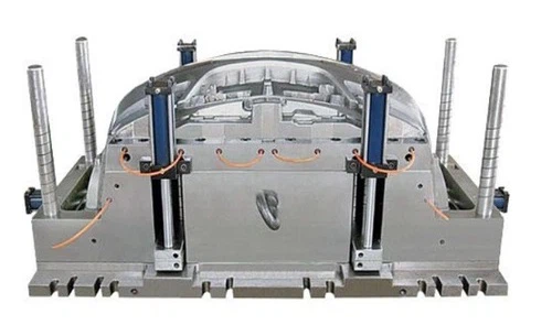

Related Mould Products
If you're also interested in other types of automotive moulds, we've got you covered. Check out our Rear Bumper Mould and Compression Molds For Automotive. And of course, if you're specifically looking for a Car Front Bumper Mold, we have a wide range of options available.
Conclusion
Designing a reasonable parting line for a front bumper mould is a combination of art and science. It requires a good understanding of the bumper's design, ejection requirements, aesthetics, and mould manufacturing processes. By following the steps outlined in this blog and considering the factors we've discussed, you can create a parting line that results in a high - quality bumper and a smooth manufacturing process.
If you're in the market for a front bumper mould or have any questions about parting line design, don't hesitate to reach out. We're here to help you with all your automotive mould needs.
References
- Injection Molding Handbook by O. John Hruska
- Automotive Body Engineering by Dr. Ferdinand Porsche