

Optimizing the design of a plastic spool mould is a critical process that can significantly impact the quality, efficiency, and cost - effectiveness of plastic spool production. As a seasoned plastic spool mould supplier, I have witnessed firsthand the importance of every step in the mould design process. In this blog, I will share some key strategies and considerations for optimizing the design of a plastic spool mould.
Material Selection for the Mould
The first step in optimizing the design of a plastic spool mould is choosing the right material. The material should have high hardness, wear resistance, and corrosion resistance to ensure a long service life of the mould. Tool steels such as P20, H13 are commonly used for plastic spool moulds. P20 is suitable for general - purpose moulds, offering good machinability and polishability. H13, on the other hand, is often used for high - performance moulds that require better heat - treating properties and resistance to thermal fatigue, especially when dealing with high - volume production and complex spool designs.
Understanding the Plastic Spool Requirements
Before starting the mould design, a thorough understanding of the plastic spool requirements is essential. This includes the size, shape, wall thickness, and surface finish of the spool. For example, if the spool is to be used for winding thin wires, it may require a very smooth surface finish to prevent wire damage. The wall thickness of the spool should also be carefully considered, as uneven wall thickness can lead to warping and other defects during the injection - molding process.
Gate Design
The gate is the entry point for the molten plastic into the mould cavity. Proper gate design is crucial for ensuring uniform filling of the cavity and minimizing defects in the final product. There are several types of gates, such as direct gates, edge gates, and submarine gates.
- Direct Gates: These are the simplest type of gates and are suitable for small - to medium - sized spools. They provide a large cross - sectional area for the molten plastic to flow, which can reduce the pressure drop during filling. However, they may leave a large gate mark on the spool, which may require additional finishing operations.
- Edge Gates: Edge gates are located at the edge of the spool and are commonly used for larger spools. They offer better control over the filling pattern and can reduce the risk of jetting (a phenomenon where the molten plastic forms a stream instead of filling the cavity evenly).
- Submarine Gates: Submarine gates are hidden gates that are cut off automatically during the ejection process. They are ideal for applications where a clean surface finish is required, as they leave minimal gate marks on the spool.
Cooling System Design
An efficient cooling system is vital for optimizing the design of a plastic spool mould. The cooling system helps to solidify the molten plastic quickly and uniformly, which can improve the cycle time and reduce the risk of warping and shrinkage. The cooling channels should be designed to provide uniform cooling throughout the mould cavity.
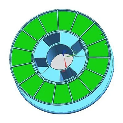
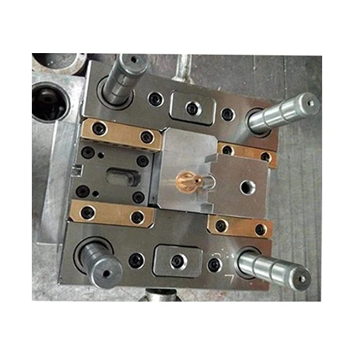
- Baffles and Inserts: Using baffles and inserts in the cooling channels can improve the heat transfer efficiency. Baffles can direct the coolant flow to areas that need more cooling, while inserts can be made of materials with high thermal conductivity to enhance heat dissipation.
- Coolant Flow Rate and Temperature: The coolant flow rate and temperature should be carefully controlled. A higher flow rate can increase the heat transfer rate, but it may also increase the pressure drop in the cooling system. The coolant temperature should be maintained at an optimal level to ensure proper solidification of the plastic.
Ejection System Design
The ejection system is responsible for removing the finished plastic spool from the mould. A well - designed ejection system can prevent damage to the spool and ensure smooth production.
- Ejector Pins: Ejector pins are the most common type of ejection mechanism. They should be placed in areas where the spool has sufficient strength to withstand the ejection force. The size and number of ejector pins should be determined based on the size and shape of the spool.
- Ejector Sleeves: Ejector sleeves can be used for spools with holes or bosses. They provide a more uniform ejection force and can prevent deformation of the spool during ejection.
Mold Flow Analysis
Mold flow analysis is a powerful tool for optimizing the design of a plastic spool mould. It uses computer - aided engineering (CAE) software to simulate the injection - molding process and predict the behavior of the molten plastic in the mould cavity.
- Filling Pattern: Mold flow analysis can help to identify potential filling problems, such as air traps, jetting, and uneven filling. By adjusting the gate location, size, and other design parameters, the filling pattern can be optimized to ensure uniform filling of the cavity.
- Weld Lines and Sink Marks: Weld lines and sink marks are common defects in plastic injection - molded parts. Mold flow analysis can predict the location and severity of these defects, allowing the designer to make necessary adjustments to the mould design to minimize their occurrence.
Cost - Benefit Analysis
While optimizing the design of a plastic spool mould, cost - benefit analysis should also be considered. Some design improvements may require additional investment in materials, manufacturing processes, or equipment. However, these improvements may also lead to higher - quality products, reduced production costs in the long run, and increased customer satisfaction.
- Long - Term Savings: For example, investing in a high - quality cooling system may increase the initial cost of the mould, but it can significantly reduce the cycle time and energy consumption during production, resulting in long - term savings.
- Customer Requirements: The design should also be balanced with the customer's budget and requirements. If the customer has a tight budget, some non - essential design features may need to be simplified or eliminated.
Case Studies
Let's take a look at some real - world examples of optimizing the design of plastic spool moulds.
- Injection Plastic Spool Bobbin Mould: For an Injection Plastic Spool Bobbin Mould, the design team used mold flow analysis to optimize the gate location and size. By moving the gate to a more strategic position, they were able to reduce the filling time and eliminate air traps, resulting in a higher - quality bobbin with fewer defects.
- Plastic Bobbin Coil Mold: In the case of a Plastic Bobbin Coil Mold, the cooling system was redesigned to include baffles and inserts. This improved the heat transfer efficiency and reduced the cycle time by 20%, leading to significant cost savings in production.
- Cable Spool Mould: For a Cable Spool Mould, the ejection system was optimized by using ejector sleeves instead of ejector pins. This prevented deformation of the spool during ejection and improved the overall quality of the cable spools.
Conclusion
Optimizing the design of a plastic spool mould is a complex but rewarding process. By considering factors such as material selection, gate design, cooling system design, ejection system design, and using tools like mold flow analysis, high - quality plastic spool moulds can be created. These moulds can produce plastic spools with better quality, higher efficiency, and lower costs.
If you are in the market for a plastic spool mould, I encourage you to reach out to discuss your specific requirements. Our team of experts is ready to work with you to design and manufacture the perfect mould for your needs. Whether you need an Injection Plastic Spool Bobbin Mould, a Plastic Bobbin Coil Mold, or a Cable Spool Mould, we have the experience and expertise to deliver a solution that meets your expectations.
References
- Throne, J. L. (1996). Plastics Mold Engineering Handbook. Marcel Dekker.
- Rosato, D. V., & Rosato, D. P. (2000). Injection Molding Handbook. Kluwer Academic Publishers.
- Beaumont, J. P. (2007). Injection Molding Troubleshooting Handbook. Hanser Publications.